
Choosing a Butterfly Valve is not just a matter of matching pipe size. The wrong seat, disc, or actuator can cause leakage, excessive pressure loss, or difficult maintenance. A valve handling clean water may behave very differently in a line carrying abrasive slurry or hot process fluid. Small details matter.
Industry guidance offers a practical starting point. The U.S. Department of Energy’s Improving Pumping System Performance: A Sourcebook for Industry emphasizes evaluating pumps and piping as a connected system, rather than selecting components in isolation. For valve design and testing, engineers commonly consult API 609, ASME B16.34, and ISO 5208. These references address design, pressure boundaries, and leakage testing; they do not replace application-specific engineering review. Check the current editions and confirm which requirements apply to your system.
This guide examines the factors that shape a sound selection: fluid properties, pressure and temperature, flow control, end connections, seat material, and operating frequency. It also considers manual, pneumatic, and electric actuation, along with installation space and maintenance access. A clear specification helps suppliers compare like with like. That sounds simple. It isn’t. Even experienced teams can overlook cycling frequency or solids in the fluid. The best choice depends on actual operating conditions, not a catalog’s broadest claim.
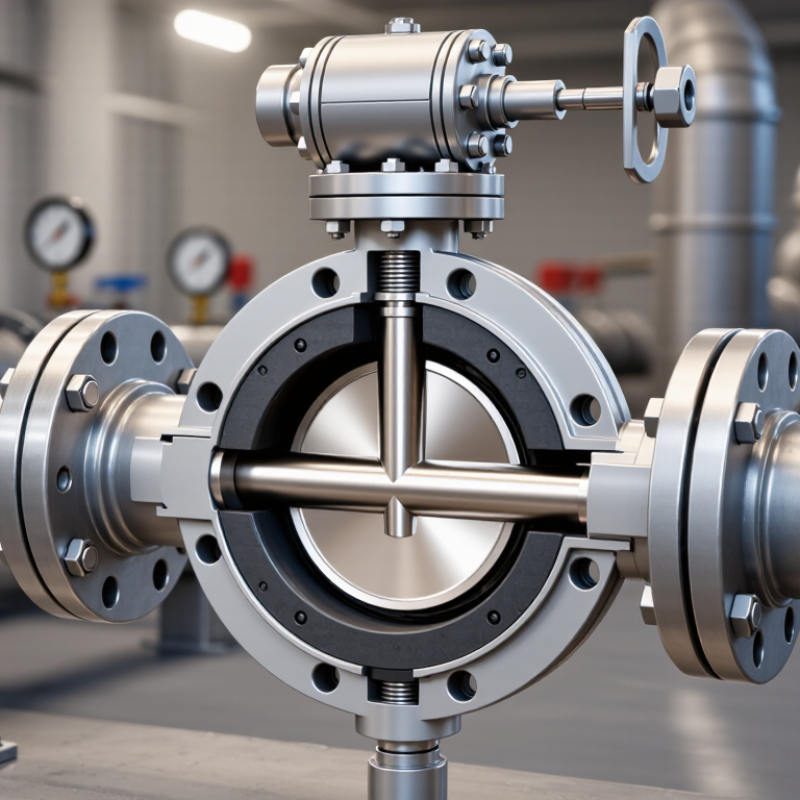
A butterfly valve should be selected for the conditions it will actually face, not just the pipe size. Record the normal and peak pressure, temperature, flow rate, and how often the valve will move. Not just the nameplate. A line carrying warm water during steady operation behaves differently from one with frequent starts, stops, or pressure surges. These details affect the valve body, disc, seat, and actuator.
Check the fluid itself. Clean water, abrasive slurry, and chemically active liquids place different demands on materials and sealing surfaces. Note suspended solids, concentration, and any cleaning chemicals used in the line. That matters. A seat compatible with the process fluid may still wear quickly if solids repeatedly pass across it. Review the manufacturer’s material data and operating limits against the full temperature and pressure range, including short-term extremes.
Also define the valve’s job. Is it mainly isolating flow, or will it regulate flow for long periods? Throttling can create noise, vibration, and uneven wear if the valve is poorly sized for the operating point. Consider available space, pipe connections, actuator power, and the required fail position. In the field, control settings sometimes differ from drawings, so verify conditions with operators and recent process records. Where data is uncertain, flag the assumption rather than treating it as fact. A qualified engineer can check sizing and pressure-drop calculations before selection.
Choose the disc and seat for the job the valve must perform. Concentric, resilient-seated designs often suit clean water and straightforward isolation. Double-offset designs reduce disc-to-seat rubbing during operation. Triple-offset, metal-seated designs may suit higher temperatures or frequent cycling. Not interchangeable. Check solids, viscosity, temperature, and pressure drop at minimum, normal, and peak flow. An oversized valve may operate almost closed, making control sensitive and wear harder to predict.
The U.S. Department of Energy’s 2006 Improving Pumping System Performance sourcebook reports that pumping systems account for nearly 20% of global electrical energy demand.
Some industrial operations use 25–50% of their energy for pumping, according to the report.
That makes valve pressure loss relevant to operating costs, not just purchase price. Compare the valve’s flow coefficient curve with the required flow range and pump curve. Request coefficients tested using recognized methods, such as IEC 60534-2-3, and verify actuator torque at the highest expected differential pressure. I would treat catalog sizing as a starting point; nearby elbows and reducers can change the installed flow behavior. Field measurements help catch that gap.
The process medium should guide both valve-body and seat selection. Water, air, oils, and chemical solutions can affect materials differently, even at similar temperatures. Check compatibility against the actual fluid, including its concentration, cleaning agents, and expected impurities. For corrosive service, a corrosion-resistant body may be suitable, but the disc and shaft need review too. A compatible body cannot protect an unsuitable seat.
Match the pressure and temperature ratings to operating conditions, not just normal readings. Include start-up surges, pressure changes, and the possibility of vacuum. The valve’s allowable rating may also depend on its seat material and size. Compare the full assembly data with the line conditions, and confirm the details with the supplier when conditions are unusual. A chart can still mislead if it omits concentration or temperature changes. That detail is easy to miss.
Tips: Write down the medium, concentration, temperature range, pressure, and cleaning cycle before comparing options. Note any suspended solids; they can wear seats or affect shutoff. Leave a margin where conditions vary, but don’t assume more rating automatically means a better fit. Recheck the choice after process changes.
| Process Medium or Service | Typical Body Material | Typical Disc Material | Seat or Liner Option | Why This Combination May Fit | Key Checks Before Selection |
|---|---|---|---|---|---|
| Clean water, HVAC water, and general utility service | Ductile iron or cast iron | Ductile iron with a protective coating or stainless steel | EPDM | EPDM is commonly used for water service and offers good resistance to water and many dilute acids and alkalis. | Confirm water chemistry, temperature, disinfectant concentration, pressure, and whether the valve is suitable for potable-water requirements. |
| Seawater, brackish water, or chloride-containing service | Coated ductile iron, duplex stainless steel, or another qualified corrosion-resistant alloy | Duplex or suitable stainless steel; higher-alloy materials may be needed for severe conditions | EPDM or a service-qualified PTFE-based seat | Material selection can help manage corrosion, but chloride exposure can cause localized attack on susceptible metals. | Assess chloride level, temperature, flow velocity, crevice conditions, coating compatibility, and galvanic effects. Do not assume standard stainless steel is suitable for every seawater application. |
| Mineral oils, lubricating oils, or selected fuel services | Carbon steel, ductile iron, or stainless steel, subject to the process conditions | Stainless steel or a compatible alloy | NBR for many oil services; FKM or PTFE-based options where compatible | NBR is often used with oils and fuels; FKM can suit many hydrocarbon services. Compatibility depends on the exact fluid and formulation. | Check fluid composition, additives, aromatic content, temperature, fire-safety requirements, and seal compatibility. EPDM is generally not suitable for petroleum oils. |
| Dilute acids or alkalis | Stainless steel, lined ductile iron, or another corrosion-resistant construction selected for the chemistry | Alloy selected to match the specific chemical | PTFE or a chemically compatible elastomer | PTFE has broad chemical resistance, while elastomer suitability varies substantially by chemical, concentration, and temperature. | Identify the exact chemical, concentration, impurities, temperature, and exposure duration. Verify every wetted material, including the stem, disc, seat, and liner. |
| Air, nitrogen, or other non-corrosive gases | Ductile iron, carbon steel, or stainless steel | Ductile iron or stainless steel | EPDM, NBR, or PTFE-based seat, selected for temperature and gas compatibility | Several body and seat combinations may be suitable for clean, non-corrosive gas service. | Confirm operating and shutoff pressure, leakage requirement, temperature, gas composition, and whether the valve is approved for the intended service. |
| Steam or elevated-temperature process service | Carbon steel or stainless steel, as required by design conditions | Stainless steel or a specified high-temperature alloy | Metal seat or a specifically rated high-temperature seat design | Elastomer seats may be unsuitable for steam or high temperatures. Metal-seated designs can serve conditions beyond the limits of many soft seats, depending on construction. | Use the manufacturer’s pressure-temperature rating for the complete valve. Check steam pressure, temperature, thermal cycling, shutoff class, and end-connection limits. |
| Food, beverage, or hygienic process media | Stainless steel with an appropriate surface finish | Stainless steel | Food-contact-compliant EPDM or PTFE-based material, as specified | Hygienic service requires suitable wetted materials and a design compatible with the cleaning and sanitizing process. | Verify applicable food-contact requirements, cleanability, surface finish, cleaning chemicals, temperature, and any required hygienic certifications. |
| Abrasive slurry or solids-bearing liquid | Wear-resistant or lined construction chosen for the slurry | Wear-resistant alloy or protected disc, as specified | Replaceable resilient liner or another slurry-rated seat design | Slurry service can accelerate erosion and wear; standard water-service trim may have a short service life. | Review solids size and concentration, abrasiveness, velocity, settling risk, valve orientation, and maintenance access. Confirm the design is intended for throttling if used that way. |
Selection note: Material suitability and pressure-temperature limits depend on the exact valve design, size, trim, applicable standard, and process conditions. Confirm the complete valve’s published pressure-temperature rating and chemical compatibility with the valve supplier before specifying or installing it.
For a butterfly valve, choose actuation around the job it must perform. An on/off valve may need only a quarter-turn electric or pneumatic actuator. Throttling service needs stable positioning, suitable feedback, and enough torque across the full pressure range. Check the valve’s torque data at startup and under worst-case conditions; a comfortable safety margin matters more than matching actuator size to pipe diameter alone. Not every valve is a good control valve.
The U.S. Department of Energy’s 2014 Bandwidth Study reports that motor-driven systems account for about 68% of electricity use in U.S. manufacturing. That figure covers plant-wide motor systems, not valve actuators alone, but it highlights why power demand and operating frequency deserve attention. For frequent cycling, compare electrical energy use, air consumption, and maintenance needs. For modulating control, confirm that the positioner’s signal matches the control system, and review the valve’s flow characteristic against the process range. ISO 5211 specifies actuator mounting interfaces; it does not confirm that an actuator is correctly sized. A useful detail to verify. I have seen selection discussions focus on interface fit while overlooking fail position: decide whether the valve should move open, closed, or remain in place when power or air fails. That decision can be less obvious than it first appears.
Before selecting a butterfly valve, check how it will fit the pipe and surrounding equipment. Measure the pipe’s inside diameter, flange spacing, and available clearance for the handle or actuator. A valve that fits on paper may still be difficult to operate beside a wall or support bracket. Leave room for movement and future inspection.
Compatibility depends on more than pipe size. Match the body and disc materials to the fluid, its temperature, and operating pressure. Confirm that the seat material suits the expected service; an incompatible seat can wear, swell, or leak. For abrasive or corrosive fluids, ask a qualified supplier or engineer to review the conditions. Small details matter. I once saw a “standard” replacement become a delay because its face-to-face dimension differed from the existing valve.
Plan maintenance access before installation. Operators should be able to reach the actuator, fasteners, and nearby isolation points without removing other equipment. Check the manufacturer’s instructions for installation direction, bolt tightening, and inspection intervals. Keep a record of operating conditions and any leakage or unusual torque. Maintenance needs vary. A valve in clean water service may need less frequent attention than one handling solids, but local conditions can change that assumption. Build in access, even if the first inspection seems far away.
Compare the number of practical checks to review in each decision area.
How to use this chart: The bars count the checks listed below; they are not performance ratings or industry benchmarks.
WhatsApp us