What Are Cross Rollers and How Do They Work?
Cross Rollers, also called crossed roller bearings, guide motion where accuracy, stiffness, and compact size must coexist. Their rollers sit alternately at 90-degree angles inside a V-shaped raceway. This arrangement carries radial, axial, and moment loads through one bearing. Imagine a camera stage moving across a polished rail. The motion feels controlled, without the visible wobble found in a poorly supported assembly.
Technical documentation from THK and IKO shows why this design suits robot joints, semiconductor equipment, measuring instruments, and precision rotary tables. ISO 281:2007 provides the established method for evaluating rolling-bearing rating life. However, calculated life is not a complete performance promise. Lubrication, contamination, mounting accuracy, preload, and temperature can change the real result. Small errors multiply.
Bearing researcher Tedric A. Harris described the bearing as “the heart of the machine.” That idea fits Cross Rollers closely. The bearing does not merely reduce friction. It determines how accurately a machine transfers force and position. A 2024 industry outlook from Grand View Research also identifies robotics and automation as strong growth areas for precision bearing demand. Yet market growth should not replace engineering judgment. A catalog load rating may look impressive, but it cannot rescue a twisted housing or uneven bolt tightening.
This guide explains the structure, load paths, operating principles, selection factors, and common failure risks of Cross Rollers. The choice is not always obvious. Real performance begins with the application, not the product label.
Definition and Basic Structure of Cross Rollers
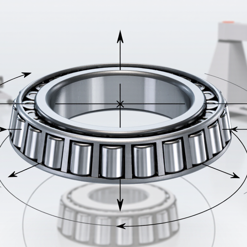
Cross rollers are precision rolling elements arranged inside a specialized bearing assembly. Their name comes from the crossed direction of neighboring cylindrical rollers. One roller lies at 90 degrees to the next. This alternating pattern allows the bearing to handle radial, axial, and moment loads within a compact space. The geometry is simple. The load path is not.
A typical cross roller bearing contains an inner race, an outer race, cylindrical rollers, and a separator or retainer. The raceways guide each roller along a precise line of contact. Because the rollers touch the raceways across narrow lines, the bearing can provide high stiffness with relatively low friction. The rollers also resist tilting forces, which is useful in positioning tables, inspection equipment, and robotic joints. In practical assembly work, I would check the raceway surfaces for dents, contamination, and uneven preload. Small defects can create noticeable vibration.
The rollers do not simply spin freely in random directions. Their orientation controls how forces move through the bearing. A controlled preload removes unwanted clearance, but excessive preload increases heat and running resistance. Alignment still matters. A clean, rigid mounting surface supports smooth motion, while a slightly distorted housing may shorten service life. The term “cross roller” can sound universal, yet internal separator designs and load ratings may differ considerably. That detail deserves careful verification.
How Cross Roller Bearings Distribute Loads
What Are Cross Rollers and How Do They Work?
How Cross Roller Bearings Distribute Loads
Cross roller bearings use cylindrical rollers arranged at alternating 90-degree angles. One roller row supports load in one direction, while the next handles the perpendicular direction. This arrangement lets one bearing manage radial, axial, and overturning forces within a compact space. The simple explanation is useful, but incomplete. Actual load distribution depends on preload, raceway accuracy, lubrication, and mounting stiffness.
When a force enters the bearing, each roller contacts the raceway along a narrow line. Several rollers share the force instead of allowing one point to carry everything. Radial loads engage rollers positioned against inward movement. Axial loads activate the crossed roller row. A tilting moment creates uneven pressure across the bearing. Rollers near the loaded edge carry more force. Others carry less. That is normal. Excessive preload, however, increases friction, heat, and wear.
During maintenance inspections, clean raceways and accurate seating remain essential. Small errors matter. Misalignment can make a theoretically balanced bearing behave unevenly. Smooth movement does not always prove equal load sharing. Temperature rise, running torque, and vibration can reveal contamination or incorrect preload. Engineers should compare operating loads with static and dynamic ratings, while checking shaft stiffness and housing deformation. The crossed layout improves rigidity, but it does not remove the need for careful design.
The Step-by-Step Motion of Cross Rollers
What Are Cross Rollers and How Do They Work?
Cross rollers are cylindrical rollers arranged in alternating directions between two precision raceways. This structure supports radial, axial, and moment loads in one compact assembly. The rollers move along straight contact lines, rather than sliding across a broad surface. That geometry helps reduce friction and limits unwanted play.
The Step-by-Step Motion of Cross Rollers
When an external force reaches the carriage, the load transfers into the upper raceway. The first roller set carries force in one direction. The next set works at a right angle, supporting the load from another direction. As the carriage advances, each roller rotates around its own axis while traveling along the raceway. The retainer spaces the rollers evenly and prevents direct contact between neighboring rollers.
The movement is controlled, not perfectly frictionless. A light preload removes clearance between the rollers and raceways. This improves stiffness, but excessive preload can increase resistance and heat.
Lubrication forms a thin film over the contact surfaces, while clean raceways protect the rolling path from abrasive particles. The path is precise. However, installation errors can change the result. Uneven mounting surfaces may create local pressure and shorten service life.
In real applications, engineers check alignment, load direction, stroke length, and lubrication intervals before selecting a suitable cross roller assembly. Careful inspection still matters, even when the mechanism appears simple.
Advantages, Limitations, and Typical Applications
What Are Cross Rollers and How Do They Work?
Cross roller bearings use cylindrical rollers arranged at right angles. Each roller carries load along a narrow contact line. This arrangement supports radial, axial, and moment loads in one compact assembly. Preloaded raceways reduce clearance, improving stiffness and positioning accuracy. The design is common in rotary tables, robotic joints, inspection stages, and precision positioning equipment.
Their main advantage is controlled motion in limited space. Cross rollers can deliver low friction and high rotational accuracy. They also resist tilting better than many conventional bearing layouts. The 2024 World Robotics report recorded 541,302 industrial robot installations worldwide in 2023. That growth increases demand for compact, repeatable motion components. However, the statistic does not prove every robot needs cross rollers. Application details matter.
Limitations deserve equal attention. Rollers need clean raceways, correct preload, and accurate mounting surfaces. Dust, uneven tightening, or shaft misalignment can create local stress and early wear. ISO 281 defines basic rating life at 90% reliability, not guaranteed service life. That distinction is easy to miss. Short-stroke motion may also cause uneven lubricant distribution and false brinelling. High-speed rotation can generate heat, while excessive moment loads reduce fatigue life. In medical imaging, semiconductor equipment, and machine tools, engineers often choose cross rollers for stiffness, but they must verify load cycles, speed, contamination control, and installation accuracy. Small design compromises can become expensive failures.