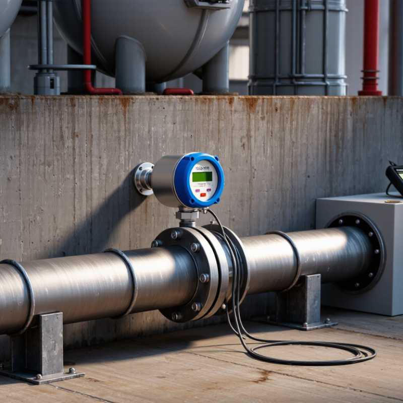
Choosing the best Clamp On Water Meter begins with the pipe, not the product brochure. A meter that works perfectly on clean steel may struggle on an aging, coated pipe. Real sites are rarely ideal. They contain rust, scale, vibration, air pockets, and limited installation space.
Flow-measurement analyst Jesse Yoder has emphasized a practical principle: “Ultrasonic flowmeters measure flow without obstructing the pipe.” That advantage explains their popularity in water networks, cooling systems, irrigation lines, and temporary audits. A Clamp On Water Meter can be installed outside the pipe, avoiding shutdowns, cutting, and additional pressure loss.
Still, “non-invasive” does not mean effortless. Pipe material, diameter, wall thickness, liner condition, and water quality directly affect signal strength. Confirm these details before choosing a model. Check the manufacturer’s sensor range carefully. Measure the pipe with a caliper when records seem unreliable.
Accuracy matters, but so does repeatability. A meter should produce stable readings during morning demand peaks and quiet nighttime flow. Look for clear installation guidance, diagnostic signals, data logging, and calibration support. Battery life also matters in remote chambers.
Small details matter.
I have seen specifications appear impressive while field installation remained awkward. That is where product selection needs honest reflection. The cheapest meter may become expensive after repeated repositioning, weak signals, or uncertain readings. A dependable Clamp On Water Meter should fit the application, the technician, and the maintenance plan—not just the sales sheet.
Choosing the best clamp-on water meter starts with understanding how it works.
The device measures flow from outside the pipe, without cutting the line or draining the system. Two transducers press against the pipe wall. They send ultrasonic signals upstream and downstream. The meter compares their travel times. Flowing water makes one signal arrive slightly faster. That difference becomes a velocity reading. The instrument then combines velocity with the pipe’s internal area to estimate flow rate. No moving parts are inside.
Accuracy depends on more than the display. Pipe diameter, wall thickness, lining, and water quality affect the signal path. A full, clean pipe usually provides stronger readings. Air bubbles, sediment, rust, or partial filling can create unstable results. In field work, careful surface cleaning often matters more than complicated settings.
Measure the pipe instead of guessing. Enter the correct material and dimensions. Install sensors on a straight section, away from pumps, valves, elbows, and reducers. A few millimeters can matter.
When comparing meters, check the flow range, sensor size, data logging, temperature limits, and verification method.
Portable units suit temporary surveys, while fixed systems support continuous monitoring. “Easy to install” can be misleading. Poor coupling gel, uneven mounting, or incorrect spacing may distort results. Verify readings against a trusted reference when possible. Review several flow conditions, not one convenient moment.
Clamp-on measurement is practical, but it is not magic. Its limits deserve attention.
How to Choose the Best Clamp On Water Meter?
Identifying your pipe, flow, and measurement requirements is the practical starting point. Measure the outside diameter with calipers, not by eyesight. Record the pipe material, wall thickness, lining, and insulation. Steel, plastic, and lined pipes can produce different ultrasonic signals. A quick visual estimate is tempting, but it can be wrong.
Check the expected flow range, minimum flow, pressure, temperature, and water quality. A meter designed for high flow may respond poorly during nighttime demand. Confirm whether you need temporary checking, leak detection, process monitoring, or billing-grade accuracy. Clamp-on installation avoids cutting the pipe, but the sensor still needs a clean, stable surface. Straight pipe is helpful. Nearby valves, pumps, elbows, and air pockets may disturb readings. In field work, installation conditions often matter more than the advertised accuracy.
Tips: Clean away rust, paint flakes, and loose insulation before mounting the sensors. Use the manufacturer’s spacing calculation for your exact pipe data. Test the reading against a trusted reference when possible. Keep a record of pipe details and installation position. Small errors in wall thickness can affect the result. When the signal is weak, do not assume the meter is defective; check alignment, coupling, and flow stability first.
| Selection Dimension | What to Identify | Typical Data or Range | Recommended Clamp-On Configuration | Important Check |
|---|---|---|---|---|
| Pipe outside diameter | Measure the external diameter of the pipe, not only the nominal pipe size. | Common water-pipe sizes include:
| Choose transducers whose specified diameter range includes the actual outside diameter. | Nominal diameter varies by pipe standard, material, and wall thickness. Confirm the meter’s supported diameter range before installation. |
| Pipe material | Identify whether the pipe is carbon steel, stainless steel, ductile iron, copper, PVC, HDPE, or another material. |
| Use a sensor frequency and mounting method approved for the pipe material and diameter. | Paint, rust, scale, lining, and air gaps can weaken the ultrasonic signal. Remove loose coating and use suitable acoustic coupling compound. |
| Pipe wall thickness and lining | Determine the wall thickness and whether the pipe has cement mortar, rubber, epoxy, plastic, or other internal lining. | Typical water-pipe wall thickness may range from a few millimetres on small pipes to more than 10 mm on large industrial pipes. | Enter accurate wall-thickness and lining information into the meter, where required. | A thick or poorly bonded lining can change the ultrasonic path. If the thickness is unknown, obtain pipe records or use an ultrasonic thickness gauge. |
| Measured fluid | Confirm that the line contains clean or relatively clean liquid and that the pipe remains full. | Water applications may include:
| Use transit-time ultrasonic measurement for clean water with limited suspended solids or bubbles. | Partially full pipes, heavy aeration, or excessive suspended solids can interrupt the signal and reduce reliability. |
| Flow velocity | Estimate the minimum, normal, and maximum velocity in the pipe. | A practical water-system design range is often about 0.3 to 3 m/s; many ultrasonic meters can cover a wider range, commonly around 0.01 to 10 m/s, depending on the model and installation. | Select a meter whose stated operating range covers both the lowest expected flow and the maximum operating flow. | Very low velocity may approach the meter’s zero-flow sensitivity, while very high velocity can increase turbulence and pressure-related installation errors. |
| Approximate flow rate | Calculate flow from pipe internal diameter and expected velocity. | Q = v × πD² ÷ 4 Example: a 100 mm internal-diameter pipe at 1 m/s carries approximately 7.85 L/s, or 28.3 m³/h. | Compare the calculated minimum and maximum flow with the meter’s published flow range and accuracy specification. | Use internal diameter, not outside diameter, for flow calculations. Wall thickness and lining reduce the flow area. |
| Required accuracy | Decide whether the meter is for indication, system balancing, leak detection, or custody-transfer-style measurement. | Typical portable or fixed clamp-on ultrasonic installations may specify approximately:
| For billing or regulatory measurement, verify the applicable legal metrology approval and calibration requirements. | Actual accuracy depends on pipe data, straight-run conditions, flow profile, signal quality, calibration, and installation quality. |
| Pipe condition | Inspect corrosion, scale, dents, welds, coating, insulation, and surface roughness. | Best results normally come from a sound, round pipe with a clean and firmly bonded surface. | Install sensors on a smooth section and remove loose rust, dirt, or flaking paint before coupling. | Do not mount directly over a heavy weld seam, damaged section, or loose external coating. |
| Installation location | Check for sufficient straight pipe upstream and downstream of valves, pumps, elbows, reducers, and tees. | A common starting guideline is approximately 10 pipe diameters upstream and 5 pipe diameters downstream from major disturbances. | Prefer a full, completely flooded section with stable flow and minimal swirl. | Shorter straight runs may be possible, but they can increase error. Follow the selected meter’s installation instructions. |
| Pipe orientation | Identify whether the pipe is horizontal, vertical, or sloped and determine the likely location of trapped air. | Vertical upward flow is generally preferable to downward flow when a vertical installation is necessary. | On horizontal lines, place sensors on the side of the pipe rather than at the very top or bottom. | Air at the top and sediment at the bottom can reduce signal quality or cause unstable readings. |
| Sensor mounting method | Determine whether the pipe diameter and installation space allow a V, Z, or alternative acoustic path. |
| Choose the mounting path recommended by the meter after entering pipe diameter, material, wall thickness, and fluid data. | Maintain the specified sensor spacing and align both transducers accurately with the pipe axis. |
| Temperature and pressure | Check the minimum and maximum water temperature, ambient temperature, and line pressure. | Typical building-water systems may operate near 5–30°C, while chilled-water systems can be colder and industrial systems may be hotter. | Select transducers, cables, enclosure, and coupling compound rated for the actual operating conditions. | The pipe must remain full at operating pressure. Verify sensor and electronics ratings separately. |
| Power and output requirements | Identify whether the meter will be portable, battery-powered, or permanently installed. | Common outputs include pulse, frequency, 4–20 mA, relay, USB, RS-485, or other digital communication interfaces. | Match the output to the building-management system, data logger, PLC, or field-maintenance process. | Confirm supply voltage, battery duration, cable length, ingress protection, and data-logging capacity. |
| Measurement objective | Define whether the measurement is temporary troubleshooting or continuous monitoring. |
| Choose a portable or permanently mounted arrangement according to measurement frequency and access conditions. | For long-term installations, protect cables and sensors from vibration, weather, impact, and unauthorized adjustment. |
| Verification before purchase | Prepare a complete pipe and operating-condition record. | Required information should include:
| Use the completed data sheet to confirm compatibility before ordering or scheduling installation. | A clamp-on meter is non-invasive, but it is not automatically suitable for every pipe. Signal quality and installation conditions should be checked on site whenever possible. |

Choosing the best clamp-on water meter starts with understanding the water and pipe conditions. A transit-time ultrasonic meter suits relatively clean water and measures flow between two sensors. A Doppler meter works better when suspended particles or air bubbles reflect the signal. For clean water, Doppler technology may produce unstable readings.
I have found that accuracy depends heavily on installation quality. Measure the pipe’s outside diameter carefully, then enter the correct material and wall thickness. Remove rust, paint flakes, and scale from the sensor area. Apply enough coupling gel to eliminate air gaps. Place both sensors straight and firmly against the pipe. Small alignment errors matter. Follow the recommended upstream and downstream distances whenever possible. Nearby elbows, pumps, and valves can disturb the flow profile.
Installation methods also affect long-term reliability. Temporary straps allow quick testing, but they may loosen during vibration or temperature changes. A fixed mounting frame provides better repeatability for permanent monitoring. After installation, compare the meter with a trusted reference, such as a calibrated tank or a verified inline meter. Record pipe conditions, sensor spacing, flow rate, and signal strength. I once accepted a stable display without checking the reference reading. The result looked convincing but was wrong. That mistake reinforced an important lesson: a smooth number is not automatically an accurate number.
A reliable clamp-on water meter begins with compatibility, not purchase price. Check the pipe’s outside diameter, material, wall thickness, and internal lining. Steel, copper, plastic, and lined pipes can produce different ultrasonic responses. Measure carefully. A small error may affect the signal path and reading accuracy. Confirm the meter supports the expected flow range, temperature, and pressure conditions. Straight pipe length also matters because nearby valves, pumps, and elbows can disturb the measurement. Follow the installation guide and record the sensor spacing for future checks.
Inspect the sensor straps, cables, and enclosure during scheduled site visits. Remove dirt, condensation, or loose insulation around the contact area. Reapply coupling gel when the manufacturer requires it.
I once assumed a stable reading meant a perfect installation. That assumption was too simple.
Compare the meter with a trusted reference during commissioning and after major pipework changes. Keep calibration records and note unusual flow patterns.
Choose outputs that match the existing control system, such as pulse, analog, or digital communication. Check sampling rates, storage capacity, alarm functions, and remote access requirements. Clear timestamps help operators compare night flow, peak demand, and leakage indicators. Protect connected devices with access controls and updated software.
Connectivity is not automatically value. A crowded dashboard can hide important changes. Test data transmission before relying on it for maintenance planning or operational decisions.
Choosing a clamp-on water meter starts with the total cost, not the purchase price. A non-invasive meter can reduce shutdowns because technicians avoid cutting pipes or draining lines. However, thick coatings, air pockets, and poor pipe access can weaken ultrasonic signals. I have seen installation estimates change after one pipe inspection. That risk deserves a budget line.
Certification protects long-term reliability. For potable-water service, check compliance with NSF/ANSI/CAN 61 or the applicable national standard. For custody transfer, verify requirements under ISO 4064, OIML R49, or local metrology rules. Calibration should be traceable to an ISO/IEC 17025-accredited laboratory. Certificates alone are not enough. Confirm the exact pipe material, diameter, temperature range, and flow conditions tested.
Data supports careful measurement. The U.S. Environmental Protection Agency reports that household leaks can waste nearly 1 trillion gallons of water annually nationwide. The World Bank has also reported that non-revenue water commonly represents a substantial share of municipal supply, often around 25–30% in developing systems. Better measurement can reveal hidden losses, but savings depend on follow-up repairs. That assumption can fail. Compare five-year costs, including calibration, battery replacement, software, labor, and verification against a reference meter. A lower-priced unit may become expensive when readings drift or support ends. Leave room for uncertainty.
WhatsApp us